

The MVA Matrix Vertical Accumulator Package reduces installation time and cost compared to field fabricated units. At the heart of the package is the Matrix LLC™ (Liquid Level) Control Panel, providing total liquid level control. The MVA Matrix Vertical Accumulator Package is available in a complete range of vessel diameters from 16” to 144”, with or without internal pipe coils. Major components are maintained in factory inventory to enable fast on-time shipments.
MVA/MVAC Accumulator Package
Product Images

Standard MVA catalogued models range in capacity from 24 to 5,401 tons of refrigeration for ammonia depending on the high stage suction temperature and are based on a 96oF liquid feed temperature. The MVA package is a liquid collection point for the suction line returning to the compressor(s) to prevent damage to the compressor(s). It can be arranged to drain accumulated liquid to a transfer vessel or it can boil off accumulated liquid. Boiling off accumulated liquid is accomplished by adding an internal pipe coil inside the vessel. This arrangement changes the model nomenclature from MVA to MVAC.
Alternatively, depending on the system design, the internal pipe coil can be designed for use as a sub-cooling coil to sub-cool liquid refrigerant. Surge volumes for the MVA / MVAC range from 3.9 to 430.7 cubic feet.
Matrix LLC – Liquid Level Control
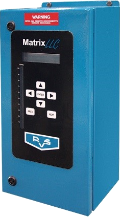
- Reads 4-20 mA signal from level probe and provide visual readout in digital and color bar indicator form on panel
- Adjustable high and low level alarms and cut outs
- Two 4-20mA analog outputs for control of proportional feed valve(s)
- Built in transformer for 24 VAC or 24 VDC power to motorized valve
- Door mounted (7) button keypad – no need to open enclosure to change settings
- Easy-to-read 16-character alphanumeric display with LED dual color bar graph
- Communication via industry standard protocol MODBUS-RTU over RS-485
- Capable of remote monitoring and control of system parameters
- UL/cUL listed NEMA 4 steel enclosure
- Factory mounted and wired requiring only a single power connection in the field
Standard Vessel Design
- ASME, 250 psig, with dual vapor relief assembly
- National Board registration
- Stainless steel nameplate bracket and standoff to prevent corrosion
- Vertical vessel configuration in 16” to 144” outside diameter range and vessel lengths of 85” to 195”
- Internally routed oil pot vent piping reduces insulation cost and potential for shipping damage (not available on MVA-16)
Oil Pot
- ASME, 400 psig, with single, replaceable, cartridge style vapor relief assembly set at 50 psig
- Relief discharge piped internal to the main vessel
- Optional dual relief assembly and/or relief to atmosphere
Liquid Level Column
- Level indicating column with valves, level eyes, frost shields, and oil drain
- Cable type, electronic level probe as standard
- High level shutdown float switch for compressor protection
Finish
- Vessel hydrostatically or pneumatically pressure tested
- Factory package piping welded and tested in accordance with ASME B31.5
- Surface prepped to SSPC-SP6 and painted with high quality two component, high solids epoxy coating
- Entire assembly is evacuated to eliminate moisture and shipped with 15 psi dry nitrogen charge
- Boil-out or Sub-cooling coil
- 300, 350 and 400 psig vessel design rating
- Corrosion allowance on vessel shell and heads, and/or nozzles
- Post Weld Heat Treatment (PWHT)
- SA333 Grade 6 Low temperature pipe
- 1.5 kw Oil pot heater
- Radiography of pipe welds
- Seismic design
- Single of dual liquid feed assembly with hand expansion or motorized valve(s)